In this tutorial I am going to demonstrate how to make Radar using ultrasonic sound. This project is purely for fun but it can be as a handy tutorial for learning the basics of the following topics.
- Distance measuring using Arduino and Ultrasonic Sound (HC-SR04)
- Wireless transmission using 433MHz RF and Arduino
- Driving a Servo using 8051 (I have used 89c2051)
- Processing Serial communication and Graphics building
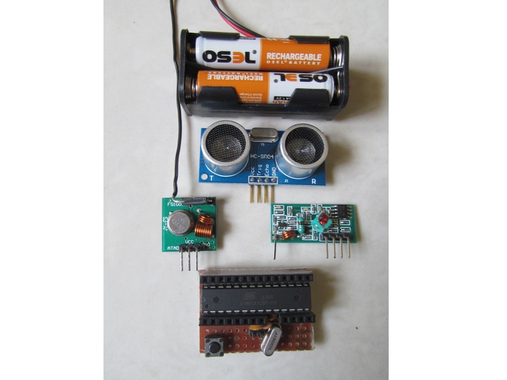
Image Gallery:
Ultrasonic Distance measuring: HC-SR04 Ultrasonic module is a very good distance measuring sensor in the range of 2-200 cm. It has built-in ultrasonic sound transmitter and receiver which is inaudible to human beings. Using the Trigger pin we can create a ping of ultrasonic sound and after reflected at nearest object it gets detected by the receiver. The Echo pin goes high whenever the module detects ultrasonic sound.
I have used “New Ping” library of Arduino to drive HC-SR04. This library directly gives the distance in cm.
433MHz RF transmission: 433MHz RF transmitter and receiver module is very low cost and popular for wireless communication in the range of 2m-100m (depending on type of module and power supply). This RF module cannot be directly connected to the RX and TX pin of the UART port of the module. The reason behind this is the RF module needs a burst training pulse and good balance of 0 and 1 to maintain DC Balance.
For the above reason I have used VirtualWire Library which gives very good performance in baud rate 2400.
Driving Continuous Servo using 8051 Microcontroller: Servo motors are mainly used for very precise angle of rotation between 0-180 degree. The angle of rotation is controlled by PWM signal. In this application I have used a continuous servo which rotates 360 degree continuously to achieve real radar appearance. Here the speed of the motor is controlled by PWM and I have used 89c2051 (20 pin 8051 family microcontroller) for generating PWM signal. The PWM signal is adjusted in a way that total time of 360 degree of rotation is 6 sec.
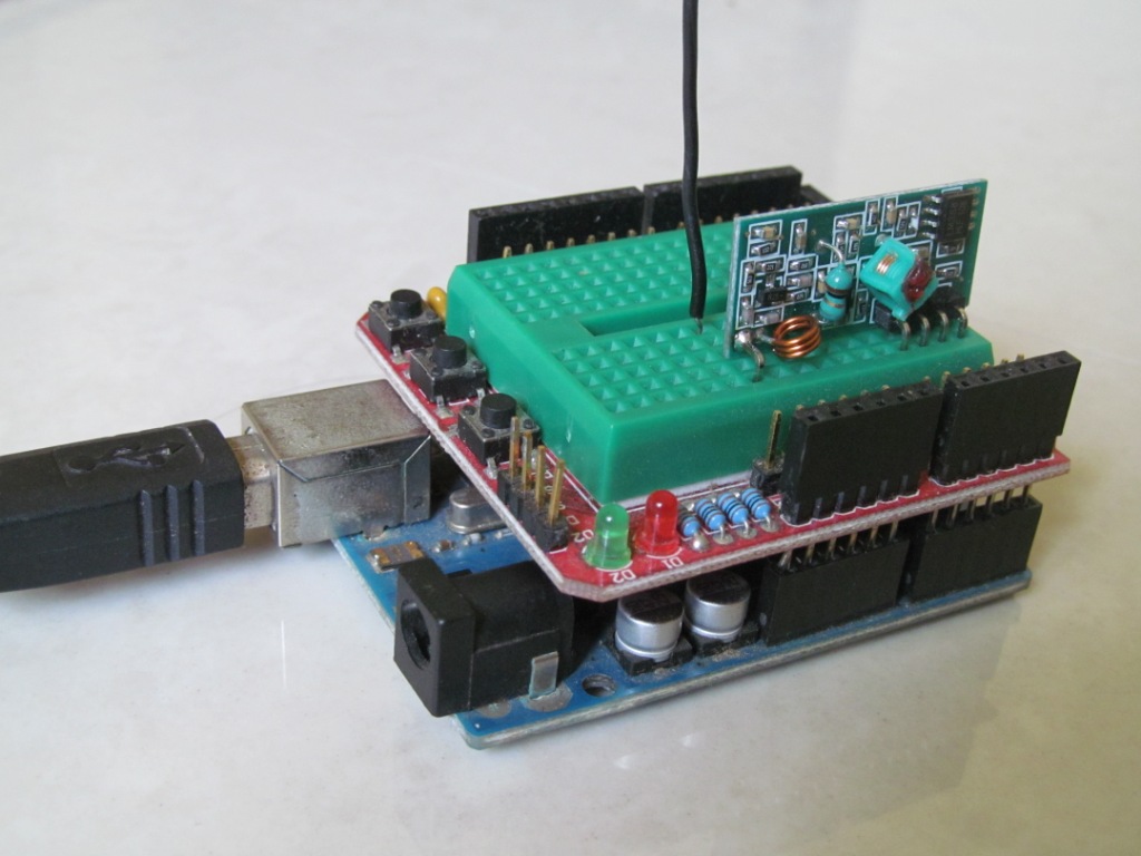
Processing Serial communication and Graphical Radar building: Processing is very popular java based cross platform programming language and development environment. It is very useful for creating Graphical User Interface quickly. There are very large communities for Processing and millions of example. The in-built serial library helps to communicate with most of the microcontroller using UART port. The Arduino at receiver end receives the distance of nearest object using 433MHz wireless module and converts it into UART signal. The Processing receives the UART signal via USB and the plots in graphical Radar.
Note: The processing environment updates frequently. So you might need to modify the program if you are using different version that I used (Version 2.0.3).
Block Diagram:
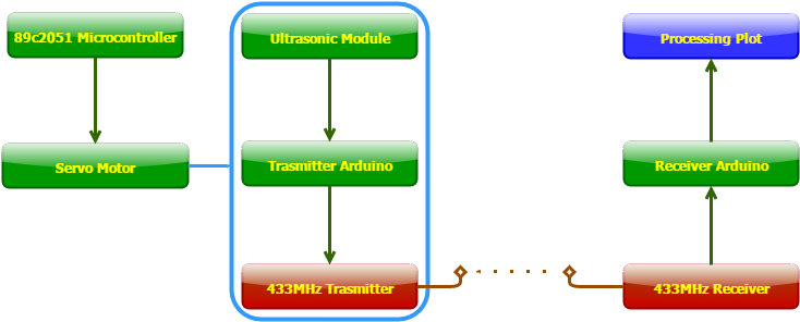
The main purpose of using wireless communication is to get continues 360° plotting. If we use wired UART communication the wire will be tangled.
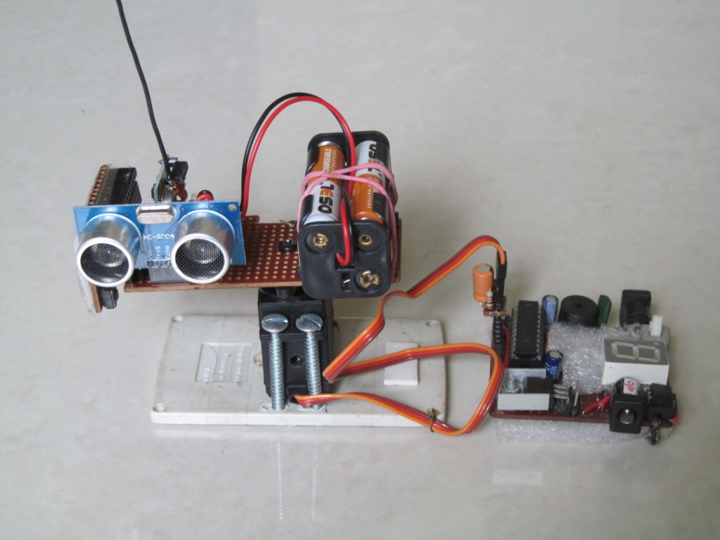
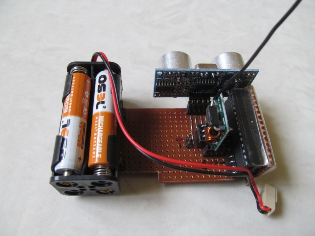
The Servo is powered and driven from fixed SMPS and 89c2051. Servo also can be driven by another Arduino. The Ultrasonic sensor, 433 MHz transmitter and transmitter Arduino fixed together on top of Servo wheel. These parts also powered from locally attached battery. Refer radar set-up at image gallery.
For transmitter side Arduino I have used Atmega328P microcontroller with Arduino boot-loader. This reduces the cost of the project significantly. To program this Arduino we need another USB to serial UART converter or another Arduino. For details please refer Arduino To Breadboard tutorial.
The rotating radar:
Plotting the radar in real time:
Source Code:
Click Here for Source Code.
Can you plss say the full project making line by line plssssssssssssssssssssssssss..
Hi Sujith,
I have described the entire project in this article. Also, all the program source code is also attached. Please let me know if you find difficulty in any particular area.