Today most of the audio and video devices are remotely controlled by IR remote. IR or Infra-Red is an electromagnetic wave like light but not visible to human eye. Cheap IR remote-controllers are widely available in the market. In this tutorial I am going to show how we can control home appliance like light, fan etc. using this remote controller.
Required components:
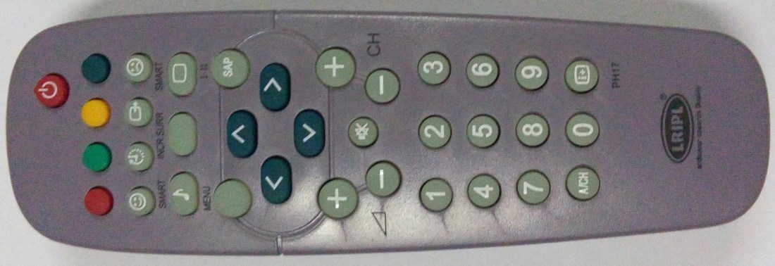
- RC5 remote (e.g. PH17)
- Atmel 89S52 microcontroller
- 40 pin IC socket
- 11.0592Mhz crystal
- 10μF capacitor (2 pieces)
- 33pF capacitor (2 pieces)
- 8.2kΩ resistance
- 222Ω resistance (7 pieces)
- 10kΩ SIP resistance
- LED (8 pieces)
- ULN2003
- 16 pin IC socket
- Relay
- TSOP 1736
- 0-12V Transformer
- 4007 diode (4 pieces)
- 7805 voltage regulator
- Veroboard
- Wire and Tools
IR Protocols: When user presses any remote key we need to send a particular message to the receiver. But there are number of IR source available in our environment like sun,light bulb, candle, any heating object. For this reason we need to encode our IR message in a way that these environments IR does not create interference and message reaches to receiver without error. Different manufacture encode in different way. But they maintain some standard known as IR protocols. Some of common IR protocols are RC5, RC6 and NEC.
In this project I have used PH17 remote which follows RC5. You can use any other RC5 remote. You may need very little code change (device address and delay).

About RC5 Protocol: RC5 protocol is consisting of 14 bit message with constant time. Address is 5 bit long and command is 6 bit long. The message is modulated with 36 kHz carrier frequency. To know more about RC5 protocols please refer my RC5 Protocol tutorial.
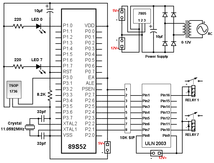
Circuit Design: The heart of this project is 8051 microcontroller. In this project I have used 89S52 which is based on 8051 microcontroller architecture with some extra flexibility. You can use any other 8051 microcontroller with same clock frequency (11.0592MHz).
TSOP1736 is very useful sensor to demodulate IR signal with 36kHz. It is an active low device. The output pin is pulled Low when IR signal with 36kHz detected. The output pin of TSOP is connected to P3_0 of microcontroller.
8 LEDs attached in P1 as output indicator. To handle 240v AC we need Relay as switch. Relay is an electromechanical device, used to isolate low voltage DC and high voltage AC or DC. To drive relay we need good amount of current which can’t be provided by microcontroller output pin. ULN2003 which generally used as unidirectional motor driver can be used as relay driver as well. It can drive upto 7 relays.
We need 12v power supply for ULN2003 and relay. 5v for all other components. A 0-12v transformer with 500mA output current capability is good enough for this. The output of transformer is converted to 12v DC using bridge circuit and filter. For 12v to 5v step-down I have used 7805 IC.

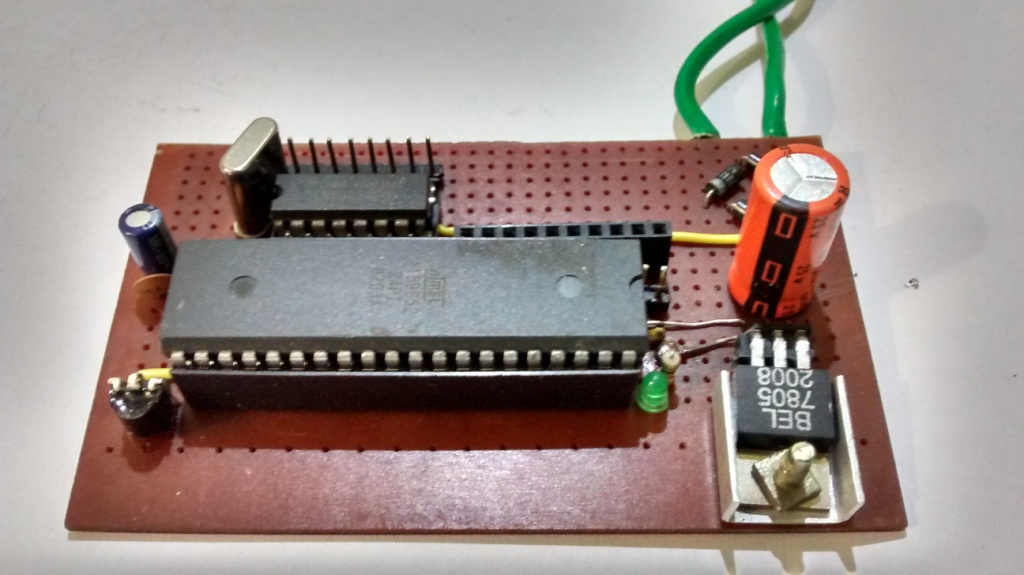
Hardware Design: The whole circuit is designed on strip line veroboard. You can use PCB layout if you are comfortable with it. Place the components wherever you like. There is no dependency of microcontroller I/O pin with the components e.g. TSOP output pin can be attached to any of the microcontroller I/O pin. Here is my prototype.
Demo:
Source Code: Decoding of any IR protocol is highly dependent with time frame. In this project I have used 11.0592MHz crystal. The code is written in C and we need a compiler to generate Hex code. Different compiler generates different Hex code and delay used in program might be different. I have used SDCC compiler which is a very good open source compiler. If you are using different compiler you might need to adjust the delay.
// Bootloader and Library Fnctions Starts Here //
#include <8051.h>
void setup();
void loop();
void main(){
	setup();
	while(1)loop();
}
// Bootloader and Library Fnctions Ends Here //
#define IR_PIN P3_0
void delayRC5(unsigned char p);
void processIR(unsigned char command);
__bit flipBit = 0;
__bit prevFlipBit = 0;

void setup(){

}
void loop(){
	unsigned char address = 0x00;
	unsigned char command = 0x00;
	unsigned char count=0x00;
	while(IR_PIN==1);	//Wait for first bit
	delayRC5(7);		//Delay for 3.024ms
	flipBit=IR_PIN;		//Reading flip bit
	for(count=0;count<5;count++){
		delayRC5(4);	//Delay for 1.728ms
		address = address << 1;
		if(IR_PIN==1)
			address = address | 0x01;
	}
	for(count=0;count<6;count++){
		delayRC5(4);	//Delay for 1.728ms
		command = command << 1;
		if(IR_PIN==1)
			command = command | 0x01;
	}
	//P1 = command;
	if(address == 0x00 && flipBit != prevFlipBit){
		processIR(command);
		prevFlipBit = flipBit;
	}
}
void processIR(unsigned char command){
	if(command == 0x01){
		P1_1 = ! P1_1;
		P2_1 = ! P2_1;
	}else if(command == 0x02){
		P1_2 = ! P1_2;
		P2_2 = ! P2_2;
	}else if(command == 0x03){
		P1_3 = ! P1_3;
		P2_3 = ! P2_3;
	}else if(command == 0x04){
		P1_4 = ! P1_4;
		P2_4 = ! P2_4;
	}else if(command == 0x05){
		P1_5 = ! P1_5;
		P2_5 = ! P2_5;
	}else if(command == 0x06){
		P1_6 = ! P1_6;
		P2_6 = ! P2_6;
	}else if(command == 0x07){
		P1_7 = ! P1_7;
		P2_7 = ! P2_7;
	}
}
//delay for 432uS. For 3.024ms call 7 times and fro 1.728ms call 4 times //
void delayRC5(unsigned char r){
	unsigned char p;
	unsigned int q;
	for(p=0;p<r;p++)
		for(q=0;q<53;q++);	//Clock 11.0592MHz
}


Could you share hex file for this project?
I have shared the hex file via email.
can u pls provide a hex file for this project??? or send it to my email id?
Hi,
I have sent you the compiled hex file.
I have a question sir , I run that program on KEIL microvision5 and it shows error on line no 13 that is “error C129: missing ‘;’ before ‘flipBit'” .HOW CAN I REMOVE THE ERROR. PLEASE HELP !
The answer is mentioned in the error message. “;” missing.
I HAVE TWO QUESTIONS:
(1).What have to do if I want to use PH03 remote of RC5 protocol?
(2). I noticed in every source code of AT89S52 Bits are look like P2^1 but here it is P2_1 Is this code suitable for 89S52 ?
PLEASE SUGGEST.
1. This decoding algorithm works only for RC5 protocol. Unfortunately, I do not have enough information about PH03 remote protocol. If it is RC5 this program will work.
2. The pin number convention is defined by compiler or assembler. I used SDCC as compiler which works with P2_1 format.
Hii Rahul!
I liked the way you wrote this code..but the fact is when i tried this code in keil uvision 5 its not working..so I did test it on development board of 8051….in proteus everywhere…but its not decoding..neither address nor command….please let me know any compiler specific changes needed ….I think other that #include of sdcc to #include except this I think there is no change required…plz help
Decoding of any IR protocol is highly dependent with time frame. In this project I have used 11.0592MHz crystal. The code is written in C and we need a compiler to generate Hex code. As you mentioned you are using keil uvision 5 or proteus I believe your compiler is also different (in my case I am using SDCC as compiler with M-IDE). Different compiler generates different machine code or hex code. My algorithm is very basic and highly dependent with delay timings. It is possible that that delay function is performing inaccurately with your compiler and you might need to adjust this function (the for loops).
Hey dude,,,,
Where I can add my custom ir signal value …I have a six digit value for a signal …so I have to add the last two digits only huh …
Sayy….my tv power button code is 1FF0B6 …now I have to put the last two digits B6 only in the code ?? …like the below
if (command ==0xB6)
{
}
I am not sure where did you got the code. The above code works with RC5 protocol. To know more about the protocol follow my older posts.
http://www.snrelectronicsblog.com/8051/rc-5-protocol-and-interfacing-with-microcontroller/
Dude ..I have 2 questions pls help me …in this code ….where I want put the founded RC5 protocal value ….
And the second question is … actually I have 89s52 mcu ….I want to make a home automation using IR ….and I have NEC ir remote …this is my project kindly help mee!!!!!
Plz…ans this two questions ..
Thanks in advance 😅😅
RC5 and NEC protocol is completely two different protocol. You can not expect to decode a NEC IR remote with a code written specific to RC5.
I have written an article regarding NEC decoding algorithm with example code for 89s51 / 89s52 microcontroller. You can take this as reference for your project.
http://www.snrelectronicsblog.com/8051/nec-protocol-and-interfacing-with-microcontroller/
Dear i have 12Mhz crystal oscillator ,let me know how to change in c file
You need to change q<53 in delayRC5 function. You need to modify in a way this function gives 3.024ms delay. You can use an oscillator for this.
How to include 8051.h library. It does not show in sketch->include library menu.
8051.h should be present in default building environment. You need to include at the beginning of your code only.
I like to make remote control ac 230v fan speed control using AT89C2051. Please help me for coding & software..
You can use the provided code for IR decoding. To control the speed you can use either Digital Dimmer or PWM with TRIAC.
I like to make remote control ac 230v fan speed control useing arduino. Please help me for coding & software.
Hi Ishwarlal,
Building IR receiver using Arduino is much more easier. There are multiple IR decoder library for Arduino available in internet. You can choose any one of them and you have to write very full lines of code according to your requirement. Simply you can edit their example code.
From hardware perspective you need to replace 8051 microcontroller and its associate components with Arduino. You can use ULN 2003 as relay driver.
Is this code is uaed for at mega16 MC instead of using 8051.?
No, this code is used in AT89S52 (8051 family microcontroller) with 11.0592MHz crystal oscillator.
i am a beginner
so can you please explain me the code.
i am planning to do this as a project.
Hi Bhavana,
As you mentioned that you are a beginner I would suggest to go through some tutorial for basic C programming and embedded system. This program is very simple and self explanatory. If you are unable to understand any specific section please let me know, I will try to explain.
Hey, Rahul great job. I want to control intensity of light by TV remote using micro controller(PIC/ 8051). How much time it will take and how much cost you will charge?
Hi Jay,
Here are the few options that can be used to control light intensity.
1. The easiest way is to use digital dimmer module available in market. You can use 8051 or PIC microcontroller for this. You only have to pass the intensity value in binary form to the module. This will cost you approx Rs. 500/- extra.
2. The second way is PWM dimming using TRIAC. Though 8051 does not have PWM hardware you can implement this by software. The drawback of this method is you only can use resistive load (filament bulb) for reliable output.
Hi,
This isn’t a full proof code. You are using delay functions for the decoding the signals. This is highly unreliable as you’ll have to use ‘trial and error’ technique every time you change the platform to compile.
But on the other hand, this is a good code when you consider for non-commercial/educational purposes.
I HAVE A QUESTION!!!!!! HOW DID YOU BURN THAT CODE ON THE MICROCONTROLLER? ALSO CAN YOU PLEASE TELL HOW MUCH WILL IT COST TO PREPARE THE WHOLE PROJECT FROM A SCRATCH…… PLEASE REPLY SOON
Hi Swati,
Here is the answer to your questions.
1. To burn the code you need 8051 burner. The burner differs depending on the microcontroller manufacturer. I have used Atmel 89S52. There are plenty of cheap 89S52 burner available in eBay.
Alternatively if have Arduino board you can make your own burner. Here is one example
http://www.instructables.com/id/ARDUINO-AS-A-8051-PROGRAMMER/?ALLSTEPS
2. The approximate cost of the project is Rs 800/- excluding the burner and tools.
this code is working in keil microvision
can u please tell how u did it in keil