Today water is one of the precious resources. In this tutorial I am going show how we can make a very simple water level indicator which not only shows the current water level in water tank but also helps to save water from overflowing while filling it. This is very cheap project and the total cost of the components is around 2$.
Required components:
- 7404 IC (NOT Gate)
- 7408 IC (AND Gate)
- 1MΩ Resistance(4 Piece)
- 222Ω Resistance(3 Piece)
- LED (Red, Yellow, Green)
- Piezo Buzzer
- 0-12V Transformer (200mA)
- AC Socket and switch
- 4007 diode (4 pieces)
- 10μF capacitor
- 7805 voltage regulator
- Veroboard
- Wire and Tools
- PVC Pipe
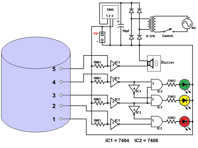
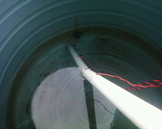
Circuit Design: The circuit is based on logic NOT and logic AND gate. For these I have used 7404 IC which contains 6 NOT gates and 7408 IC which contains 4 AND gates. Using five wires at different height of tank the circuit can sense 5 different level of water. Here the wires work as sensor. The sensor at the bottom is connected to the ground of the circuit. Rest four sensors are connected to the input of four NOT gates. These NOT gate inputs are pulled high by 1MΩ resistance. The output of these NOT gates are connected with two more NOT gates and three AND gates as per below circuit diagram. The output of the AND gates are connected with LEDs via 222Ω resistance. Use bigger LEDs for better visibility.
The circuit needs 5v power supply with 200mA current capability. I have used a 0-12v transformer for this. The output of transformer is converted to 12v DC using bridge and filter circuit. This 12v DC stepped down to 5v by using 7805 IC.

How the circuit works: When the tank is empty all NOT gate inputs (1-4) are high through the 1MΩ resistance and all AND gates one input is low. Hence all LEDs go off. After starting to fill the tank, water touches the second sensor. In this condition water is grounded with first sensor and because of the resistance of water is lower than 1MΩ, the input of first NOT gate goes low and output goes high. This makes one input of first AND high. Another input of this AND gate is already high as it is connected to sensor 3 using two (1 & 5) NOT gates. This two high input makes AND output high the Red LED turned on.
When water touches third sensor the Yellow LED goes on, in the same way of Red LED. At the same time one input of the first AND gate goes low via fifth NOT gate and Red LED goes off. Similarly when water touches fourth sensor the Green LED goes on and Yellow goes off. When water reaches at the top sensor the buzzer turned on. Using the AC switch we can turn it off
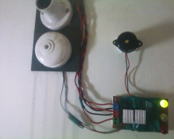
My Prototype: I am using this circuit at my home for more than 6 years. Here is the gallery of my prototype.


Hi, I hope you still reply to comments.
I wish to make my pump come on when the water level gets to sensor 5, by using a 5v in relay 15A-125V out to switch on my aquarium pump to empty the reservoir and shut off the pump when it gets to sensor 2. I wish this to be fully automatic. My portable AC unit creates a lot of water and it goes into a bucket. Sometimes we are not at home and the bucket overflows. I notice in your drawing the directions of the diodes, Is there an error? I hope this is not too complicated to redesign the shematic for me.
Thank you in advance.
Paul
Hi Paul,
As per your use-case the easiest way is to use an Arduino board (5v variant). It will allow you write custom logic when to turn on and off your pump. To detect the water level still you can 1M resister and a Not Gate. I believe 5v current will not harm your fishes. If it does you can use some non touch technique like ultrasonic distance sensor or a sealed water pressure sensor.
Is there any problem if I directly connect 5V source without using IC 7805.And also I want only buzzer sound i don’t want automatic.So I think I can give dc supply without using AC.am i correct?
Yes, you can provide a 5V DC source directly, it will work fine.
do we have to implement on veroboard?
Yes, this is a simple circuit and it can be implemented in veroboard.
This is an awesome post and it helped me.