NEC protocol was developed by NEC corporation. This protocol provides very good reliability by doubling address and commands.
Specifications: Address → 8 Bit in standard mode and 16 Bit in extended mode.
Command → 8 Bit
Modulation → Pulse Distance Modulation
Carrier → 38 kHz
Modulation: NEC protocol uses Pulse Distance Modulation at 38 kHz carrier frequency, hence all bit length are not same. A logical One is represented by 560 μs filled with burst of carrier, followed by 1690 μs being idle. Logical Zero is represented by 560 μs filled with burst of carrier, followed by 560 μs being idle. So the length of logical Zero is half of the logical One.

Apart from the logical zero and one, a header bit is used at the beginning of pulse train. The header bit is 9ms filled with burst of carrier, followed by 4.5ms being idle. This bit also helps the receiver to auto adjust gain.
A 560μs burst of carrier is used at the end of pulse train to indicate termination.
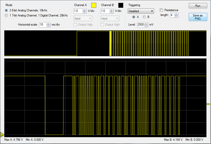
Protocol: The following diagram is a typical example of NEC protocol in Standard Mode with 40H address and E0H command.

For an address or command the LSB is transmitted first and MSB at last. When a key pressed in the remote following bits transmitted sequentially.
- Header Bit
- 8 Bit Address
- 8 Bit logical inverse of Address
- 8 Bit Command
- 8 Bit logical inverse of Command
- Termination pulse.
Note that address and command are transmitted twice by inverting them. This feature not only enhances the reliability but also make number of zero and one same for both the address and command. Hence total length of the message remains constant.
Here is TSOP output (inverted) scope view of key 0

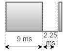
Unlike RC-5 and RC-6 protocol the message is transmitted only once even user holds the key pressed. Instead a repeat bit is send repeatedly. The repeat bit is consist of 9ms burst of carrier followed by 2.25 ms idle and followed by 560μs burst.

The repeat bit is sent in every 108ms. The following diagram is a typical example of repeat.

Extended Mode : NEC address can be extended upto 16 bit if reliability is not a concern. This is done by utilizing both the address and inverse address field. But in this case total message length may not be same. In this way the number of different device address can be upto 65536.
The command field is not extendable and only 256 different keys are possible.
Decoding Using Microcontroller : To use RC6 remote in our electronics project we need decode the protocol and get the command from there. We may need the address and flip bit also depending the functionality of the project. So here I am going to show how we can decode RC6 using Arduino.
NEC Decoding Using Arduino : Decoding RC6 using Arduino is very easy as there are plenty of libraries are available. One of the most famous is KS Library. Click Here for Github location.
NEC Decoding Using 8051: 8051 is another popular and cheap general purpose microcontroller used today. In case of decoding any IR protocol the timing is crucial factor. I have used 11.0592Mhz crystal so that we can use UART properly if we need it in future. The exact time frame can be created using Assembly language by calculating machine cycle. But I have seen in my experience that assembly code is very difficult to maintain. For this reason I have written the code in C. We can generate hex code by compiling the C code. But different compiler generates different hex code. I have used SDCC which is a free compiler. If you are using different compiler then you might have to adjust the count used in the program.
Flowchart:

Source Code:
// Bootloader and Library Fnctions Starts Here //
#include <8051.h>
void setup();
void loop();
void main(){
	setup();
	while(1)loop();
}
// Bootloader and Library Fnctions Ends Here //
#define IR_PIN P3_7
void processIR();
void repeatIR();
unsigned int count = 0;
unsigned char index = 0;
unsigned int address = 0;
unsigned int command = 0;
__bit startBit = 0;

void setup(){
	//Init Code
}
void loop(){
	count = 0;
	while(IR_PIN){
		count++;
	};
	if ((count > 630) && (count < 700)){ //Critical count 665
		startBit = 1; // set flag
		address = 0; // reser old address
		command = 0; // reset old command
	}
	else if ((count > 300) && (count < 360)){
		repeatIR();
	}
	else if(startBit){
		if(index < 16){ // reading address
			if((count >= 210) && (count <= 270)){
				if(index > 1){
					address = address << 1;
				}
				address |= 1;
			}else if ((count >= 40) && (count <= 100)){
				if (index > 1){
					address = address << 1;
				}
			}
		}
		else{ // reading command
			if((count >= 210) && (count <= 270)){
				if(index > 16){
					command = command << 1;
				}
				command |= 1;
			}else if ((count >= 40) && (count <= 100)){
				if (index > 16){
					command = command << 1;
				}
			}
		}
		index ++;
	}
	if(index >= 32){ // full message received
		processIR();
		index = 0;
		startBit = 0;
	}
	while (!IR_PIN); // wait until sensor flips
}
void processIR(){
	unsigned char address1 = (0xff & (address >> 8));
	unsigned char address2 = 0xff & address;
	unsigned char command1 = (0xff & (command >> 8));
	unsigned char command2 = 0xff & command;
	//P1 = address1;
	//P1 = address2;
	//P1 = command1;
	P1 = command2;
}
void repeatIR(){
	P3_2 = !P3_2;
}
Hi sir,
I have seen code of NEC decoder. please note thet you have defined P3_7 as input for IR signal, but at the
end you have used P3_2 port pin. Is it works?
Hi Iftikhar,
Yes, this code works. The pin mismatch is a valid bug, both the pin should be the same.
Rahul….I have 89s52 and NEC remote …I want to make home automation using that …I have to submit it in next one week …kindly help me …where I can change this code to make a home automation using NEC ir remote …
Thanks !!!?
Inside the processIR() function you have access to address and command. Here you can write your custom code according to your requirement.
Hi Rahul,
1. May i know name of the software by which you captured that output graph of TSOP ?
2. May i know the name of the Receiver you used, TSOP 1738 or 1838 ?
Hi Aditya,
The software is SLO-scope which works with ‘Pololu USB AVR Programmer’. For details please refer the bellow link.
https://www.pololu.com/product/1300
I used TSOP 1738, but it should work perfectly with TSOP 1838 also.
else if ((count > 300) && (count < 360)){
repeatIR();
}
else if(startBit){
if(index < 16){ // reading address
if((count >= 210) && (count <= 270)){
if(index > 1){
address = address << 1;
}
address |= 1;
}else if ((count >= 40) && (count <= 100)){
if (index > 1){
address = address << 1;
}
}
}
Can you pls explain what exactly is meant by the above code? Why have you used count values as 630,40,100 and all? How did u derive these count values?
also which operator is this " |= " ?
pls rply ASAP!!!!
Thanks in advance!
Hi Vikrant,
The mentioned code determines if a transmitted bit is 0 or 1(or starting of pulse train and repeat bit). This is done by measuring the length of absence of carrier (refer diagram for ‘Logic 0’ and ‘Logic 1’). The count values are used as measured length.
I have determined the count values using oscilloscope and some trial and error method. This counts are actually representation of time. As I already mentioned this values might be different if you are using different Microcontroller or Crystal or C Compiler. The range of count values help to ignore minor deviation. For example the actual start bit count value is 665. Hence I kept the count range 630-700. One range should not overlap with other ranges. If you are using Atmel AT89c51 microcontroller (or exactly same architecture e.g. 89S52) with 11.0592MHz crystal and compile the code using SDCC you can use these values as is.
The “|=” operator is bitwise inclusive OR and assignment operator. The following lines are equivalent.
address |= 1;
address = address | 1;
Hi Rahul,
Thanks for replying.But i still have some doubts.
You said above, the actual start bit count is 665.How did you get that count.can you pls show the calculation of count value.
Also can u please tell the algorithm of the code?What all you did to decode each address bits.Kindly explain in detail the procedure to find the values through oscilloscope? The whole flow of code i need.
Reply ASAP!!!!
Thanks in advance!
If you write the code in assembly language you can easily find the timing diagram using clock frequency and machine cycle. But if you are writing the code in C then the assembly code is generated by the compiler (SDCC) which not very predictable. For this reason I determined the count value by oscilloscope and some trial and error method.
For an example consider the detection of start bit. From the protocol diagram you can see the length is 4500μs. Remember we only measure the second half of the pulse (where the signal is absent), because for all bits first half length is same (except the start bit). Now create a program to determine the count value. You can refer following code.
void loop(){
count = 0;
TEST_PIN = 0;
while(count<100){
count ;
};
TEST_PIN = 1;
while(count<100){
count ;
};
}
Now if you connect TEST_PIN to oscilloscope you will get a square wave. Measure the width / length of a square pulse. For me it came around 700μs.
length = 700μs.
count ~ (4500 / 700) * 100 = 642
Run the while loop for 642 times and you will get the square wave where length is around 4500μs. Now do some trial and error method by changing this 642 value until you get square wave with length exactly 4500μs. The closest value I got is 665.
For all command and address bit you can follow the same procedure. Though it is little bit time consuming process, it works perfectly. You need to determine following count values.
1. Start bit - 4500μs
2. Repeat bit - 2500μs
3. Logic 1 - 1690μs
4. Logic 0 - 560μs
Once you get all the values you can get the address and command by using my code.
I am creating the flowchart and upload as soon as it is ready.
Understood everything now.Thanks a lot!!!!! 🙂
Waiting for algorithm or flowchart.
Thanks in advance!!!
You are welcome.
I have added the flowchart.