RC-5 Protocol was developed by Philips and most used by hobbyists because of the wide availability of cheap remote and easy to decode.
Specifications : Address → 5 Bit
Command → 6 Bit
Modulation → Bi-Phase
Carrier → 36 kHz
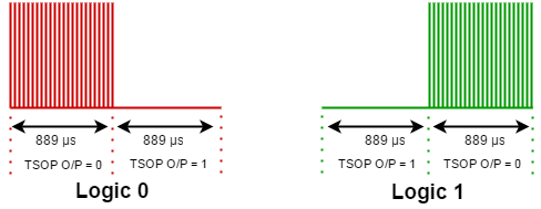
Modulation: RC-5 protocol uses Bi-Phase or Manchester coding at 36 kHz carrier frequency, hence all bit length is equal (1.778ms). A logical Zero is represented by first half (889 microsecond) filled with burst of carrier and being idle at another half. Logical One is represented by reversing the pattern.
Protocol: When a key is pressed following 14 bits transmitted sequentially
- 2 start bit
- 1 toggle bit
- 5 bit address
- 6 bit command
The figure below transmits 02H as address and 07H as command
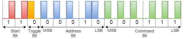
Header Field: The first two bits are start bit and these are always 1. Note that when receiver get to know there is signal half of bit time is already elapsed. This bit helps receiver to auto adjust gain.
Next bit is toggle bit. Every time a key released this bit get changed. This bit helps to understand if user has pressed and hold the button.
Address Field: Following five bits are address bit. Every different type device has different address. Here are some example.
TV → 00H and 01H
VCR → 05H and 06H
CD Player → 14H to 20H
Command Field: Last six bits are command bits and only 64 different command is possible. Hence only 64 different key is available in RC-5 protocol.
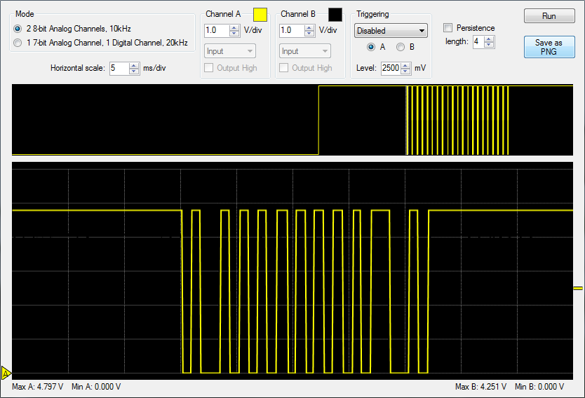
Scope View: Here is TSOP output (inverted) scope view of key 4
Decoding Using Microcontroller: To use RC5 remote in our electronics project we need decode the protocol and get the command from there. We may need the address and flip bit also depending the functionality of the project. So here I am going to show how we can decode RC5 using Arduino and 8051 Microcontroller.
RC5 Decoding Using Arduino: Decoding RC5 using Arduino is very easy as there are plenty of libraries are available. One of the most famous is KS Library. Click Here for Github location.
RC5 Decoding Using 8051: 8051 is another popular and cheap general purpose microcontroller used today. In case of decoding any IR protocol the timing is crucial factor. I have used 11.0592Mhz crystal so that we can use UART properly if we need it in future. The exact time frame can be created using Assembly language by calculating machine cycle. But I have seen in my experience that assembly code is very difficult to maintain. For this reason I have written the code in C. We can generate hex code by compiling the C code. But different compiler generates different hex code. I have used SDCC which is a free compiler. If you are using different compiler then you might have to adjust delayRC5.
Flowchart:

Source code:
// Bootloader and Library Fnctions Starts Here //
#include <8051.h>
void setup();
void loop();
void main(){
	setup();
	while(1)loop();
}
// Bootloader and Library Fnctions Ends Here //
#define IR_PIN P3_7
void delayRC5(unsigned char p);
void processIR(unsigned char command);
__bit flipBit = 0;
__bit prevFlipBit = 0;

void setup(){
	//Initial setup
}
void loop(){
	unsigned char address = 0x00;
	unsigned char command = 0x00;
	unsigned char count=0x00;
	while(IR_PIN==1);	//Wait for first bit
	delayRC5(7);		//Delay for 3.024ms
	flipBit=IR_PIN;		//Reading flip bit
	for(count=0;count<5;count++){
		delayRC5(4);	//Delay for 1.728ms
		address = address << 1;
		if(IR_PIN==1)
			address = address | 0x01;
	}
	for(count=0;count<6;count++){
		delayRC5(4);	//Delay for 1.728ms
		command = command << 1;
		if(IR_PIN==1)
			command = command | 0x01;
	}
	//P1 = command;
	if(address == 0x00 && flipBit != prevFlipBit){
		processIR(command);
		prevFlipBit = flipBit;
	}
}
void processIR(unsigned char command){
	P1 = command;
	//Custom code here
}
//delay for 432uS. For 3.024ms call 7 times and fro 1.728ms call 4 times //
void delayRC5(unsigned char r){
	unsigned char p;
	unsigned int q;
	for(p=0;p<r;p++)
		for(q=0;q<53;q++);
}
Hi Sir,
I have compiled the source code using SDCC compiler and burnt it in mico AT89s52. Unfortunately i got noting on
pressing remote. Please send me Hex file on email address if possible.
Thanks in advance.
Hi Iftikhar,
I did this project long back. Unfortunately I do not have the hex code with me.
do we have to consider the long pulse and short pulse while decoding the signal ? i have compared this code to the ones in the arduino and this doesnt consider that. i am just trying to understand how the bit detection works. i am trying to decode it with a 8051 . i have successfully decoded it with arduino and it decodes it perfectly but cant properly decode it with 8051. i am using keil c51. does changing the IDE make that much of a difference with the delay ?
I am not sure what is long and short pulse. As per my knowledge the pulse width for RC-5 protocol are always fixed (1.778ms). Although I admit that the arduino library is much more robust. Changing IDE does not make any difference. But as you mentioned you are using keil c51 I believe your compiler is also different (in my case I am using SDCC as compiler with M-IDE). Different compiler generates different machine code or hex code. My algorithm is very basic and highly dependent with delay timings. It is possible that that delay function is performing inaccurately with your compiler and you might need to adjust this function (the for loops).
I want complete data sheet for RC5 protocol. Anyone could please provide link of pdf
What changes will have to be made if I want to use Keil compiler?
Hi Vedant,
I suggest you to compile the code using SDCC. It is a GPL licensed software. You can use M-IDE Studio which works very well with SDCC.
I’m curious, this code actually uses polling to wait for the signal. while this is cool, it only makes it limited to just this function. please admin, with all begging and solicitation, could you write a code that is interrupt based? i’ll be really grateful..
Hi Moses,
In RC5 protocol the gap between two messages is 114ms which is normally high enough for processing the data. But if you really want to perform other tasks continuously you can implement this program interrupt driven in following way.
1. Connect TSOP output pin to one of the interrupt pin (P3_2 for INT0) of 8051
2. Define interrupt function definition.
void IRInterrupt(void) __interrupt 0;
3. Enable interrupt inside setup() function.
IT0 = 1; //Edge Trigger Interrupt
EX0 = 1; //Enable External Interrupt INT0
EA = 1; //Enable Global Interrupt
4. Move all code from loop() function to interrupt function and remove ‘wait for signal’.
Disable interrupt at the beginning and re-enable it at the end of this interrupt function.
void IRInterrupt(void) __interrupt 0{
EX0 = 0; //Disable External Interrupt INT0
/*
IR decode code from loop() function excluding ‘while(IR_PIN==1);’
*/
EX0 = 1; //Re-Eisable External Interrupt INT0
}
5. Perform all other task inside loop() function.