Timers are one of the most important devices in terms of bringing automation in our life. Today almost all smart home electrical appliances like fridge, heater etc. have their own inbuilt timers. But in sometime we want to control electrical devices which do not have any automation. For example running a motor for a certain time duration.
In this tutorial I am going to show how we can make a timer which can be used for almost every electrical device. The device is very easy to use and the device itself does not consume any power after it shuts down the electrical application. Because of hardware simplicity it is extremely durable. The prototype here I am showing, was made more than 5 years ago and still it is working flawlessly.
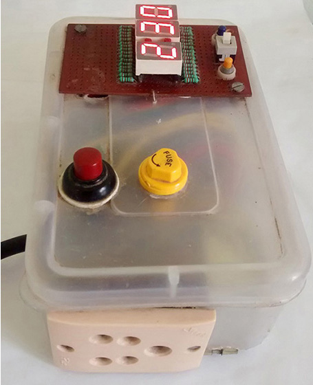
How to operate: While designing the timer device my top priority was ease of use. The AC input is provided by standard AC plug. For output I used AC female socket and any electrical appliance can attached easily.
To start the timer the red button (high voltage push switch) has to be pressed and device will run for ‘Default Time’. This default time is hardcoded in the program. For my device I kept it as 2 hours and 30 minutes. The time left to go off will be displayed in hour and minute format on 7 Segment display array. Two small push buttons are used to increase or decrease the remaining time. These buttons can be pressed at any time and it will increase or decrease 1 minute for each button press. If user keep pressed the button then time will decrease or increase continuously.
After the time is over the buzzer will alarm for 10 more seconds. During this user can extend the time by just pressing increase push button. If user does not extend time the device will be disconnected from AC power supply automatically. I did not keep any force shutdown button as it can be done by switching off the input power supply.
Required components:
- Atmel 89S52 microcontroller
- 40 pin IC socket
- 11.0592Mhz crystal
- 10μF capacitor (2 pieces)
- 33pF capacitor (2 pieces)
- 8.2kΩ resistance
- 10kΩ SIP resistance
- Common Anode 7 Segment Display (3 piece)
- LED (2 piece)
- 222Ω resistance (26 pieces)
- Passive Buzzer
- Push Switch (3 piece)
- Push Switch – High Voltage (1 piece)
- 0.5Amp fuse and socket
- AC Socket with cable
- AC Female Socket
- Relay
- 0-12V Transformer (500mA)
- AC Plug and Female Socket
- 4007 diode (4 pieces)
- 7805 voltage regulator
- Veroboard
- Wire and Tools
- Plastic container
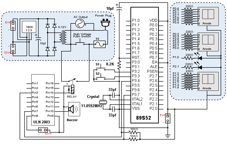
Circuit design: The heart of this project is 89S52, which is a microcontroller based on 8051 architecture. I chose this microcontroller because it is the cheapest microcontroller which has 32 I/O pin. These much I/O pins helped me to connect 7 segment displays directly to microcontroller without additional component. To keep circuit diagram clean I have separated the 7 segment display array in the circuit diagram. The port pin mapping has shown in the display section.
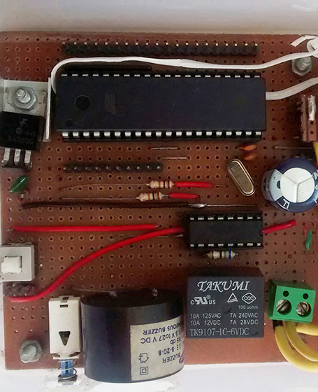
I have used electromechanical relay to handle 240v AC. This relay needs a driver which can provide higher current and I have used ULN2003 for this. To increase durability you can use semiconductor relay instead of electromechanical relay and for that you do not need ULN2003. We need 12v power supply for ULN2003 and relay. 5v for all other components. A 0-12v transformer with 500mA output current capability is good enough for this. The output of transformer is converted to 12v DC using bridge circuit and filter. For 12v to 5v step-down I have used 7805 IC.
Be careful while making AC section. Any short circuit will damage the whole circuit at once and may cause physical injury. The fuse is used to protect from short circuit. The whole system encapsulated in a plastic container to avoid electrical shock.
Here is circuit diagram of my prototype.

Source code: The code is written in C language. To generate hex code we need a compiler. I have used SDCC for this. Please note that the generated hex will differ from compiler to compiler. So if you are using different compiler you might need to adjust the time delay. Additionally the delay is also dependent on crystal frequency. If you are using different from 11.0592 MHz as I used you must adjust the time delay.
I have modularized the code for better maintainability and re-usability. In this page I am attaching main code. Click here to download the whole source code.
#include <SNR8052_v2.h>
#include <SNR7SDisp_v2.h>
#define Sec_Dot_Down P1_0
#define Sec_Dot_UP P2_1
#define Alarm P3_4
#define AC P3_7
unsigned long timerTime = 10800000; //3 Hours as default time
//unsigned long timerTime = 180000; //3 Min for test
unsigned long maxTimerTime = 14400000;  //Max time 4 Hiurs
void attachInterrupt(char interruptNo);
void updateDisplay();
void initiateShutdown();
void incrmentInterrupt(void) __interrupt 0;
void decrementInterrupt(void) __interrupt 2;
void setup(){
    Alarm = 0; // Making alerm off
    attachInterrupt(0);
    attachInterrupt(1);
    timerTime = timerTime + 60000;
}
void loop(){
    if((timerTime - millis())<60000){
        initiateShutdown();
    }
    updateDisplay();
    Sec_Dot_Down = !Sec_Dot_Down;
    Sec_Dot_UP = !Sec_Dot_UP;
    delay(500);
}
void initiateShutdown(){
    int i=0;
    updateDisplay();
    for(i=0;i<10;i++){   // 10 times for 5 sec
        Disp1_Dot = !Disp1_Dot;
        Disp2_Dot = !Disp2_Dot;
        Disp3_Dot = !Disp3_Dot;
        Alarm = !Alarm;
        delay(500);
    }
    if((timerTime - millis())<60000){
        AC = 0;
    }
    else {
        Disp1_Dot = 1;
        Disp2_Dot = 1;
        Disp3_Dot = 1;
        Alarm = 0;
    }
}
void updateDisplay(){
    int remainMin = (timerTime - millis())/60000;
    char minLeft1 = (remainMin%60)%10;
    char minLeft2 = (remainMin%60)/10;
    char hourLeft = (remainMin/60);
    write7Segment(hourLeft,1);
    write7Segment(minLeft2,2);
    write7Segment(minLeft1,3);
}
void attachInterrupt(char interruptNo){
    switch(interruptNo){
        case 0 : { // External Interrupt 0
            EA = 1; // Enabling global Interrupt
            EX0 = 1; // Enabling External Interrupt 0
            break;
        }
        case 1 : { // External Interrupt 1
            EA = 1; // Enabling global Interrupt
            EX1 = 1; // Enabling External Interrupt 1
            break;
        }
        default : {
            break;
        }
    }
}
void incrmentInterrupt(void) __interrupt 0{
    if((timerTime-millis()) > maxTimerTime){
        timerTime = millis();
    }
    timerTime = timerTime + 60000;
    updateDisplay();
    delay(200);
}
void decrementInterrupt(void) __interrupt 2{
    if((timerTime-millis()) < 60000){
        timerTime = millis() + maxTimerTime;
    }
    timerTime = timerTime - 60000;
    updateDisplay();
    delay(200);
}


using multiplexing would have been better. The header files are unnecessary and Timer 1 should be used
Hi NewtonEinstien,
Thanks for your comment.
Multiplexing of 7 Segments is definitely more versatile approach. Here I used directly I/O pin because I had enough available pins and does not need any additional component.
The header files are for modular programming pattern. ‘SNR8052_v2.h’ I created to get Arduino like programming structure. So whenever I start a new project I simply copy this file and it brings speed in development. Similarly I created ‘SNR7SDisp_v2.h’ for re-usability.
In ‘SNR8052_v2.h’ I created millis() function similar to Arduino and I am leveraging this function. This can be considered as a demonstration of solution where we need multiple update function. Timer0 and Timer1 can be used for more precise task.